Imagine you’re holding a flashlight in a dark room. When you turn it on, you see a bright beam of light. Well, light is a form of energy that makes things visible to our eyes. It’s like a messenger that carries information about the world around us.
Light is a form of electromagnetic energy that causes the sensation of vision. Some common phenomena associated with lights are:
- Image formation by mirrors
- The twinkling of stars
- The beautiful colours of a rainbow
- Bending of light by a medium
- And many more.
Properties of Light
- Electromagnetic waves do not require any medium to travel.
- Light tends to travel in a straight line.
- Light has a dual nature, i.e., wave as well as particle.
- Light casts a shadow.
- The speed of light is maximum in a vacuum. Its value is 3 × 10⁸ m/s.
When light falls on a surface, the following may happen:
A) Reflection B) Refraction C) Absorption
Reflection of Light
Have you ever wondered why you can see your reflection on a shiny surface?
The answer lies in the phenomenon of reflection. When light encounters a surface, it bounces back, allowing us to see objects and ourselves. The reflection of light is the phenomenon where light bounces off a surface and changes direction.
Laws of Reflection
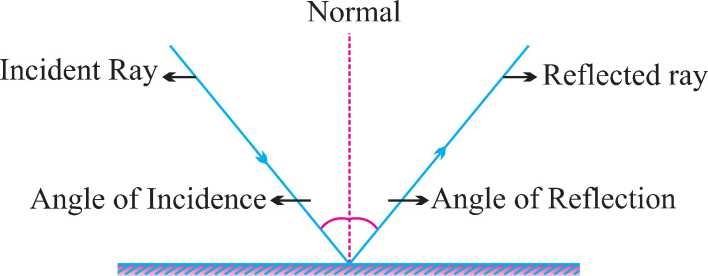
(i) Angle of incidence is equal to the angle of reflection.
(ii) The incident ray, the reflected ray, and the normal at the point of incidence all lie in the same plane.
Virtual and Real image
Image is a point where at least two light rays actually meet or appear to meet.
Image Formed by Plane Mirror
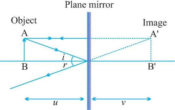
Characteristics of Image Formed by Plane Mirror
(i) Virtual and erect.
(ii) The size of the image is equal to the size of the object.
(iii) The image is formed as far behind the mirror as the object is in front of it.
(iv) Laterally inverted.
Lateral Inversion: The right side of the object appears on the left side of the image and vice-versa.

Application of lateral inversion: The word AMBULANCE is written in the reverse direction so that it can be read correctly in the rearview mirror of vehicles going in front of it.
Spherical Mirrors
- Mirrors whose reflecting surface is curved.
- There are two types of spherical mirrors:
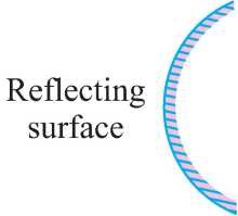
(i) Convex Mirror
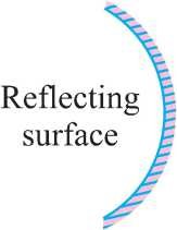
(ii) Concave Mirror
| Convex Mirror | Concave Mirror |
| Reflecting surface is curved outwards | Reflecting surface is curved inwards |
| Diverging mirror | Converging mirror |
 |  |
ccm1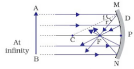 | 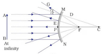 |
Properties of Concave mirror
- The reflecting surface is curved inwards.
- Converging mirror.
Properties of Convex mirror
- The reflecting surface is curved outwards.
- Diverging mirror
Common terms for Spherical mirrors
- Principal axis: The line joining the pole and center of curvature.
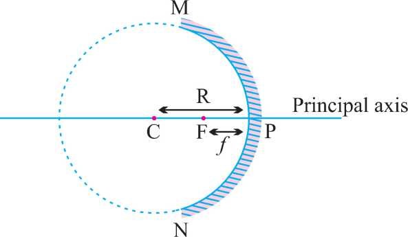
- Pole (P): The center of the spherical mirror.
- Aperture (MN): It is the effective diameter of the spherical mirror.
- Center of Curvature (C): The center of the hollow glass sphere of which the mirror was a part.
- Radius of Curvature (R): The distance between the pole and the centre of curvature.
- Focus (F): The point on the principal axis where all the parallel light rays actually meet or appear to meet after reflection.
- Focal length (f): The distance between the pole and the focus.
- Relationship between focal length and radius of curvature: f = R/2
Rules for making ray diagrams by spherical mirror
| (i) | A ray parallel to the principal axis, after reflection, will pass through the principal focus in the case of a concave mirror or appear to diverge from the principal focus in the case of a convex mirror | |
| (ii) | A ray passing through the principal focus of a concave mirror or a ray that is directed towards the principal focus of a convex mirror, after reflection, will emerge parallel to the principal axis | ccmd2 |
| (iii) | A ray passing through the center of curvature of a concave mirror or directed in the direction of the center of curvature of a convex mirror, after reflection, is reflected back along the same path | ccmd3 |
| (iv) | A ray incident obliquely to the principal axis, towards a point P (pole of the mirror), on the concave mirror or a convex mirror, is reflected obliquely. The incident and reflected rays follow the laws of reflection at the point of incidence (point P), making equal angles with the principal axis | ccmd4 |
Ray diagrams for images formed by concave mirror
| Object Position | Image Position | Nature of image | Size | Diagram | |
| (i) | When object is at infinity | At ‘F’ | Real, inverted | Point-sized or highly diminished | |
| (ii) | When object is beyond ‘C’ | Between ‘F’ and ‘C’ | Real, inverted | Diminished | |
| (iii) | When object is at ‘C’ | At ‘C’ | Real, inverted | Same size as that of object | |
| (iv) | When object is placed between ‘F’ and ‘C’ | Beyond ‘C’ | Enlarged | ||
| (v) | When object is placed at ‘F’ | At Infinity | Real, inverted | ||
| (vi) | When object is between ‘P’ and ‘F’ | Behind the mirror | Virtual, erect | Enlarged |
(iv)
Image Position –
Nature of image– Real, inverted
Size –
(v)
Image Position –
Nature of image – Real, inverted
Size – Highly enlarged
(vi)
Image Position –
Nature of image –
Size –
Uses of Concave Mirror
- Used in torches, searchlights, and vehicle headlights to get a powerful parallel beam of light.
- Concave mirrors are used by dentists to see large images of the teeth of patients. (Teeth have to be placed between pole and focus).
- A concave mirror is used as a shaving mirror to see a larger image of the face.
- Large concave mirrors are used to concentrate sunlight to produce heat in a solar furnace.
Ray diagrams of images formed by convex mirror
Rule for image formation by Convex Mirror
| (i) | A ray of light parallel to the principal axis of a convex mirror appear to diverge from the principal focus | |
| (ii) | A ray which is directed towards the focus of the convex mirror will emerge parallel to the principal axis after reflection | |
| (iii) | A ray directed towards the center of curvature of a convex mirror is reflected back along the same | |
| (iv) | A ray incident obliquely to the principal axis is reflected obliquely |
Ray diagrams of images formed by convex mirror
| Object Position | Image Position | Nature of image | Size | ||
| (i) | When object is placed at infinity | At ‘F’ | Virtual, erect | Point sized | |
| (ii) | When object is placed between pole and infinity | Between ‘P’ and ‘F’ | Virtual, erect | Diminished |
A full length image of a tall building/tree can be seen in a small convex mirror.
Uses of Convex Mirror
- Convex mirrors are used as rear view mirrors in vehicles because they always give an erect though diminished image and they have a wider field of view as they are curved outwards.
- Convex mirrors are used at blind turns and on points of merging traffic to facilitate vision of both sides of traffic.
- Used in shops as a security mirror.
Sign Convention for Reflection by Spherical Mirror Or New Cartesian Sign Convention
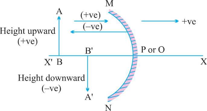
- The object is placed to the left of the mirror.
- All distances parallel to the principal axis are measured from the pole of the mirror.
- All distances measured in the direction of the incident ray (along + X-axis) are taken as positive, and those measured against the direction of the incident ray (along – X-axis) are taken as negative.
- The distance measured perpendicular to and above the principal axis is taken as positive.
- Distances measured perpendicular to and below the principal axis are taken as negative.
- Object distance = ‘u’ is always negative.
- Focal length of concave mirror = Negative
- Focal length of convex mirror = Positive
Mirror Formula
1/v + 1/u = 1/f
where, v = Image distance
u = Object distance
f = Focal length
Magnification of Spherical Mirrors
It is the ratio of the height of the image to the height of the object.
m = Height of image/Height of object
⇒ m = hi/ho
Also, m = -v/u
- If ‘m’ is negative, the image is real.
- If ‘m’ is positive, the image is virtual.
- If hi = ho then m = 1, i.e., image is equal to object.
- If hi > ho then m > 1 i.e., image is enlarged.
- If hi < ho then m < 1 i.e., image is diminished.
The magnification of the plane mirror is always + 1.
‘+’ sign indicates virtual image.
‘1’ indicates that the image is equal to the object’s size.
- If ‘m’ is ‘+ve’ and is less than 1, it is a convex mirror.
- If ‘m’ is ‘+ve’ and more than 1, it is a concave mirror.
- If ‘m’ is ‘-ve’, it is a concave mirror.
Refraction of Light
The bending of a ray of light as it passes from one medium to another is called refraction.
It is due to a change in the velocity of light while travelling from one medium to another.
The maximum velocity of light is 3 × 10⁸ m/s in a vacuum or air.
The velocity is less in the denser medium.
Some examples of refraction :
- The bottom of swimming pool appears higher.
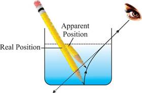
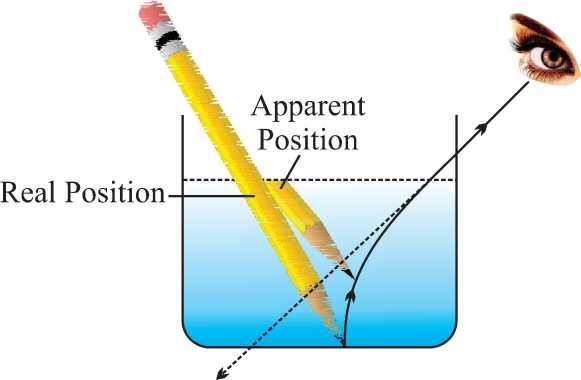
2. A pencil partially immersed in water appears to be bent at the interface of water and air.
- Lemons placed in a glass tumbler appear bigger.
- Letters of a book appear to be raised when seen through a glass slab.
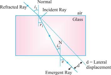
- The extent of bending of ray of light at the opposite parallel faces of rectangular glass slab is equal and opposite, so the ray emerges parallel to incident ray.
- Lateral displacement depends on :
- Refractive index of glass slab
- Thickness of the glass slab
Laws of Refraction of Light
Laws of refraction state that:
- The incident ray, refracted ray, and the normal to the interface of two media at the point of incidence all lie on the same plane.
- The ratio of the sine of the angle of incidence to the sine of the angle of refraction is constant. This is also known as Snell’s law of refraction.
- Sin i/Sin r = constant
Bending of Light Ray
According to Snell’s law, μ1 sin i = μ2 sin r
- Some examples of refraction :
- The bottom of swimming pool appears higher.
- A pencil partially immersed in water appears to be bent at the interface of water and air.
- Lemons placed in a glass tumbler appear bigger.
- Letters of a book appear to be raised when seen through a glass slab.
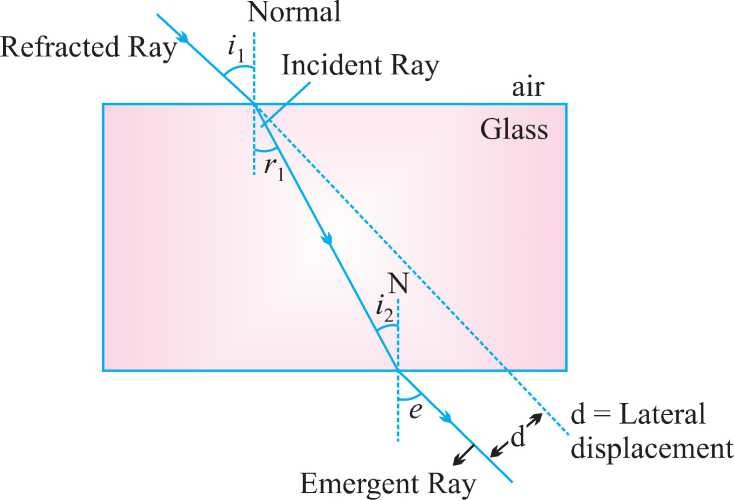
- The extent of bending of ray of light at the opposite parallel faces of rectangular glass slab is equal and opposite, so the ray emerges parallel to incident ray.
- Lateral displacement depends on :
- Refractive index of glass slab
- Thickness of the glass slab
(i) If light passes from rarer to the denser medium:
μ1 = μR and μ2 = μD
so that,
⇒ ∠i > ∠r
In passing from rarer to a denser medium, the ray bends towards the normal.
(ii) If light passes from denser to rarer medium μ1= μD and μ2 = μR
⇒ ∠ i < ∠r
In passing from denser to rarer medium, the ray bends away from the normal.
The refractive index depends on the nature and density of the medium and color of light. The refractive index is maximum for violet and minimum for red light.
What is Refractive Index?
Refractive index, also called the index of refraction describes how fast light travels through the material.
The Refractive Index is dimensionless. For a given material, the refractive index is the ratio between the speed of light in a vacuum (c) and the speed of light in the medium (v). If the refractive index for a medium is represented by n, then it is given by the following formula:
- When a light ray is refracted from medium number 1 into medium number 2, the relative refractive index of medium 2 w.r.t. medium 1(n21) is given by
- Similarly, the refractive index of medium 1 with respect to medium 2 is given by
- Therefore, we conclude that n21 x n12 = 1
or n21 = 1 / n12
Lenses
- A lens is a piece of any transparent material bounded by two curved surfaces or by one curved and one plane surface.
- Lens are of two types:
Convex or convergent lens
Concave or divergent lens
Terminologies
- Optical Centre: O is a point for a given lens through which any ray passes undeviated.
- Principal Axis: C1C2 is a line passing through optical centre and perpendicular to the lens.
- Principal Focus: A lens has two surfaces and hence two focal points. First focal point is an object point on the principal axis for which image is formed at infinity.
- While second focal point is an image point on the principal axis for which object lies at infinity.
- Focal Length f is defined as the distance between the optical center of a lens and the point where the parallel beam of light converges or appears to converge.
- Aperture: In reference to a lens, aperture means the effective diameter. The intensity of the image formed by a lens, which depends on the light passing through the lens, will depend on the square of the aperture, i.e., I µ (Aperture)2
Try yourself:What is the nature of the image formed by a concave mirror when the object is placed between ‘F’ and ‘C’?
- A.Real, inverted
- B.Point-sized
- C.Virtual, erect
- D.Diminished
Rules for Image Formation
- A ray passing through the optical center proceeds undeviated through the lens.
- A ray passing through the first focus or directed towards it, after refraction from the lens, becomes parallel to the principal axis.
- A ray passing parallel to the principal axis after refraction through the lenses passes or appears to pass through F2.
For Convergent or Convex Lens:
| Object | Image | Magnification |
| ∞ | F | m << – 1 |
| ∞ – 2F | F – 2F | m < –1 |
| 2F | 2F | m = –1 |
| F – 2F | ∞ – 2F | m > –1 |
| F | ∞ | m >> –1 |
| F – O | In front of lens | m > + 1 |
Image Formation for Convex Lens
- Object is placed at infinity.
Image: at F
real, inverted,
very small in size and
m ≪ –1 - Object is placed in between ∞ and 2F.
Image: real (F – 2F)
inverted,
small in size (diminished), and
m < –1 - Object is placed at 2F.
Image : real (at 2F)
inverted
equal (of same size)
(m = -1) - Object is placed in between 2F – F.
Image: real (2F – ∞)
inverted
enlarged
m > 1 - The object is placed at F.
- The object is placed in between F – O.
Image: virtual (in front of the lens)
erected
enlarge
(m > + 1)
| Given | Real | Virtual |
| u | – | – |
| v | + | – |
| h1 | + | + |
| h2 | – | + |
| m | – | + |
Image Formation for Concave Lens
Image is virtual, diminished, erect, towards the object, m = +ve
- Object is placed at infinity.
Image: At F
virtual
erect
diminished
(m ≪ +1) - The object is placed in front of the lens.Image: between F and the optical center
virtual
erected
diminished
(m < + 1)
Lens Formula
The focal length of a lens can be found by the following formula:
Where – f = Focal length of lens.
v = Distance of image from pole
u = Distance of object from pole.
Uses of Lens Formula
(i) Put the correct signs of known variables according to the sign conventions.
(ii) Do not put the sign of an unknown variable. The sign will automatically show up during calculations.
(iii) If the calculated sign of a variable turns out positive, then the variable calculated is on the other side of the lens, i.e., on the opposite side to the object. However, if the calculated variable is of a negative sign, then it is on the same side as the object.
Combination of lenses
Two thin lenses are placed in contact with each other
Power of combination:
P = P1 + P2
1/F = 1/f1 + 1/f2
Use sign convention when solving numericals.
Two thin lenses are placed at a small distance a.
1/F = 1/f1 + 1/f2 – a/f1f2
P = P1 + P2 – a P1P2
Use sign convention when solving numerical.
Power of Lens
The power of a lens is defined as the reciprocal of the focal length of the lens. Focal length should always be measured in meters.
The unit of power of the lens is 1/meter, which is called a dioptre.
Magnification of Lens
Magnification is defined as the ratio of the height of the image and the height of the object represented by M.
Leave a Reply